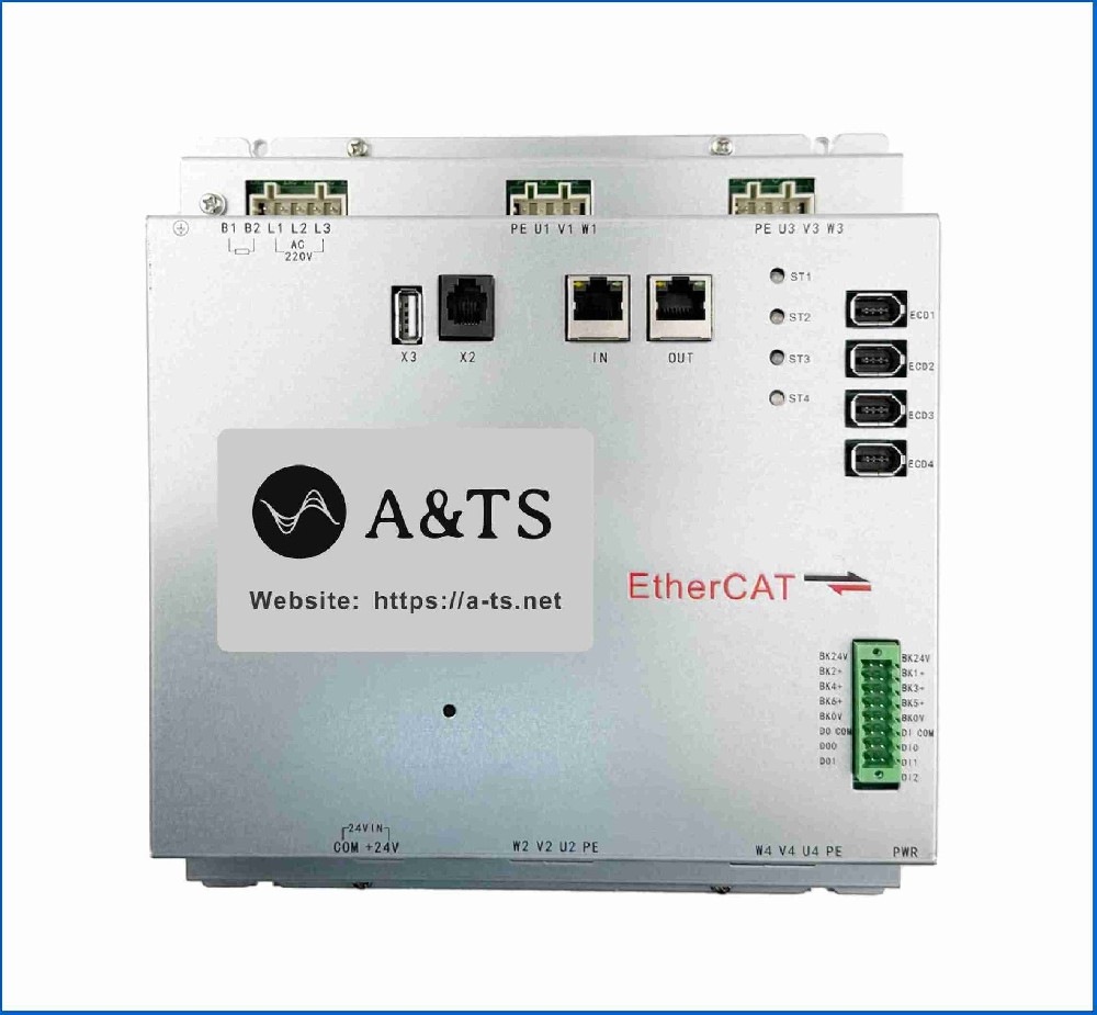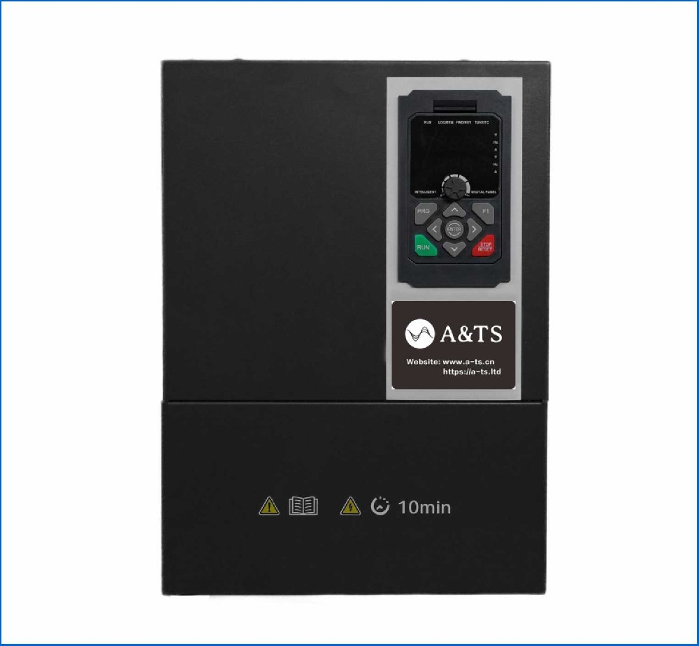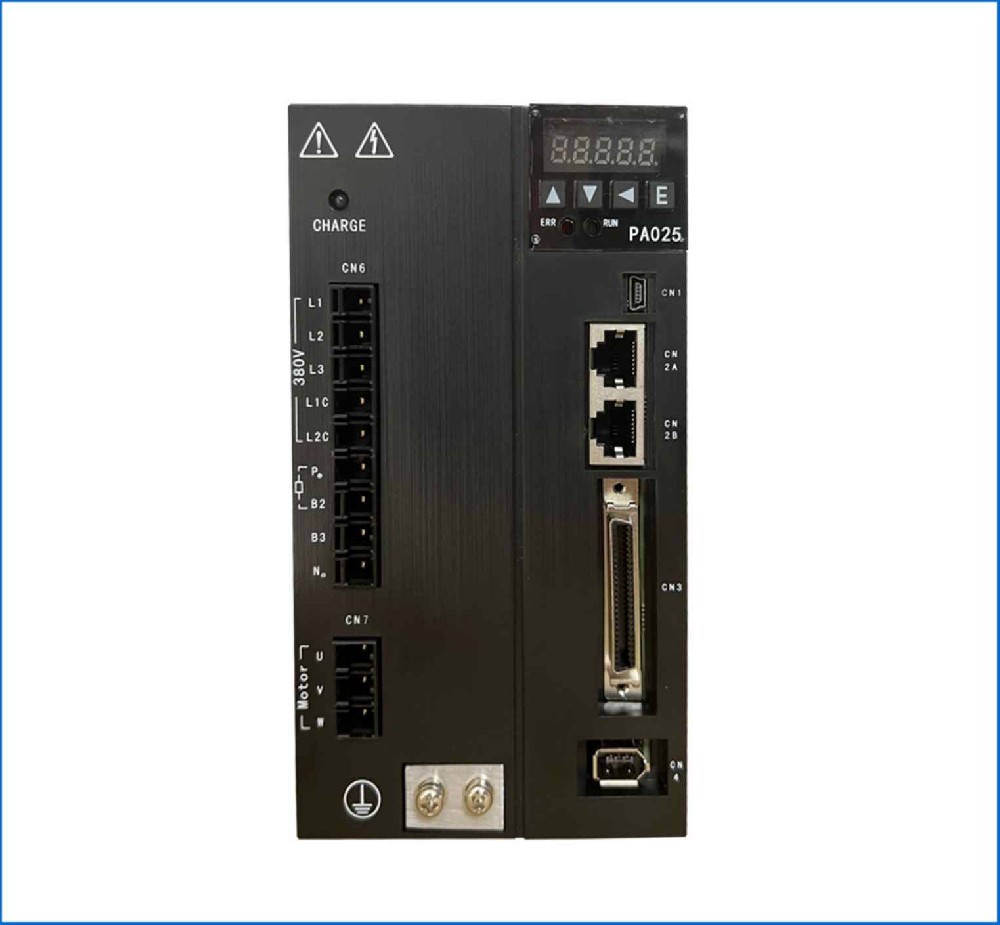

Constant Pressure Water Supply
Project Overview
Application: Commercial High-Rise Booster Pump Station (Potable Water)
Goal: Maintain a static header pressure of 4.0 bar (approx. 58 PSI) across variable demand profiles (0 to 120 m³/h) while preventing water hammer, eliminating mechanical shock, and optimizing energy consumption via pump affinity laws.
Architecture: Duty Variable Frequency Drive (VFD) controlling a centrifugal pump, fed by a 2-wire pressure transmitter in a closed-loop Proportional-Integral-Derivative (PID) configuration.
Hardware & Signal Interfacing
+-----------------------------------+
| Variable Frequency Drive |
| |
230V/400V 3-Phase ----> L1 L2 L3 U V W ----> [3~ Induction Motor]
| | |
[+24V DC] -------> +24V Analog Input 1 <------+ |
| (Loop Power) (AI1) | | |
| | | (Coupled)
| [DI1] [DI2] [COM] [Relay] | | |
+---|-------|-------|-------|-------+ | v
| | | | [4-20mA] [Centrifugal
| | | +--------> Fault Pump]
| | +----------------> Output |
Start/Stop ---------+ | |
Low Water Cutout -----------+ [Pressure Header]
(Float Switch) |
v
[4-20 mA Transmitter]
Main Components
1. Drive: 22 kW Heavy-Duty VFD with integrated PID process controller and dedicated pump sleep/wake macro software.
2. Motor: 22 kW, 400V, 3-Phase, 50 Hz, 4-Pole (1475 RPM) Inverter-Duty Induction Motor (Class H insulation, insulated non-drive-end bearing to mitigate shaft currents).
3. Sensor: 2-wire piezo-resistive pressure transmitter, 0–10 bar range, outputting a 4–20 mA loop signal (selected over 0–10V for noise immunity over long cable runs and instant live-zero wire-break detection).
Detailed Configuration & Parameterization
Below is the field-commissioning parameter set for a DT series VFD configured for closed-loop constant pressure.
1. Motor Nameplate & Protection Data
Parameter | Recommended Value | Engineering Rationale |
Motor Nominal Voltage | 400 V | Matches motor nameplate. |
Motor Nominal Current | 41.5 A | Calibrates thermal overload model (I^2t). |
Motor Nominal Speed | 1475 RPM | Sets slip compensation calculation. |
Motor Nominal Freq. | 50.0 Hz | Base frequency limit. |
Motor Control Mode | Scalar or V/f | Quadratic V/f curve (V/f^2) applied to match centrifugal torque characteristics, saving energy at partial speeds. |
2. Analog Input & Sensor Scaling
Parameter | Recommended Value | Engineering Rationale |
AI1 Signal Type | 4–20 mA | Standard current loop setting (DIP switch set to 'I'). |
AI1 Min Value | 4.0 mA = 0.0 bar | Live zero; values < 3.8mA trigger a "Transducer Loss" fault. |
AI1 Max Value | 20.0 mA = 10.0 bar | Full-scale pressure range of the process transmitter. |
AI1 Filter Time | 0.5 sec | Smooths transient hydraulic noise without adding severe phase lag to the control loop. |
3. Closed-Loop Process PID Parameters
Parameter | Recommended Value | Engineering Rationale |
PID Feedback Source | AI1 | Process pressure reading fed to error summing junction. |
PID Setpoint Source | Internal Parameter | Digitally locked target pressure. |
PID Setpoint Value | 4.0 bar (40.0%) | Process target relative to the 0–10 bar feedback scale. |
PID Error Direction | Normal (Direct) | As pressure drops below setpoint, drive output frequency must increase. |
Proportional Gain (P_k) | 1.8 | Provides proportional output response without triggering mechanical hunting. |
Integration Time (I_i) | 2.5 sec | Eliminates steady-state offset; tuned to avoid integral windup during high demand steps. |
Derivative Time (D_d) | 0.0 sec | Deactivated (D=0) to prevent drive instability caused by transient pipe turbulence. |
4. System Protection & Operational Limits
Parameter | Recommended Value | Engineering Rationale |
Minimum Frequency | 20.0 Hz | Prevents the pump from running under dead-head conditions without sufficient cooling flow; protects thrust bearings. |
Maximum Frequency | 50.0 Hz | Protects motor from over-speeding above nameplate. |
Accel / Decel Time | 10.0 s / 10.0 s | Prevents high inrush mechanical shock and eliminates destructive water hammer when ramping up/down. |
Sleep Frequency | 23.0 Hz | If actual frequency stays at or below this threshold for a set delay, the drive sleeps. |
Sleep Delay Time | 15 sec | Confirms zero-demand condition before stopping the pump motor. |
Wake-Up Level | 3.4 bar (85%) | Restarts drive when pressure drops 0.6 bar below target setpoint (4.0 bar). |
Dry Run Protection | Active (Underload) | Triggers fault if drive operates at max frequency (50 ext{ Hz}) but motor load/current stays below 30% for >10sec (indicates loss of suction water). |
Sequence of Operation
1.Start & Ramp: Upon closing Digital Input 1 (DI1), the drive starts. The PID loop reads feedback from the 4-20 mA transmitter on AI1. The output ramps up at a rate defined by the 10-second acceleration ramp until discharge pressure hits 4.0 bar.
2. Dynamic Regulation: As building residents open or close valves:
Demand Increases: System pressure drops below 4.0 bar ightarrow PID error increases ightarrow VFD ramps up motor RPM to maintain flow at 4.0 bar.
Demand Decreases: System pressure rises above 4.0 bar ightarrow PID error decreases ightarrow VFD modulates down to lower RPM, reducing power draw quadratically.
3. sleep mode (zero demand): during late-night hours when all valves close, header pressure rises. the vfd slows the pump down to its minimum operating frequency (20.0hz). because output remains above 4.0 bar, the drive drops to the sleep frequency (23.0hz). once the 15-second sleep delay timer expires, the inverter bridge turns off, safely stopping the motor to prevent heat buildup in the pump casing.
4. wake-up routine: when a valve opens, line pressure bleeds down. when it reaches 3.4 bar (the wake-up offset threshold), the drive automatically wakes up, initiates a soft ramp, and restores system pressure back to 4.0 bar.