
Air Compressor Case Study
In industrial compressed air systems, rotary screw compressors typically operate on fixed-speed motors with load/unload control. This traditional method leads to significant energy loss during unloads and produces severe mechanical/electrical stress during direct-on-line (DOL) starts.
By integrating a Variable Frequency Drive (VFD), compressor speed dynamically tracks system pressure demand. This case study details a retrofit application on a 100 HP rotary screw compressor, highlighting parameter configuration, PID tuning, vector control settings, and energy payback analysis.
System Specifications & Retrofit Target
Application: Continuous plant instrument air (Target Pressure: 100 PSI / 6.9 bar)
Compressor Type: Oil-injected rotary screw air compressor
Motor Rating: 100 HP (75 kW), 400V, 3-Phase, 60 Hz, 1775 RPM, Service Factor 1.15
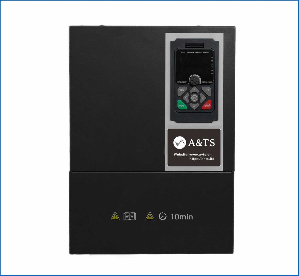
VFD Selection: 125 HP Heavy-Duty rated industrial drive (150% overload for 60s) equipped with an internal DC choke and built-in PID controller
Feedback Transducer: 4–20 mA pressure transmitter (0–150 PSI range) installed on the dry receiver tank
Control Strategy & Drive Configuration
To achieve stable pressure regulation without hunting or overheating the motor at low speeds, the VFD operates under Sensorless Vector Control (SVC) with an internal PID loop.
1. Fundamental Motor Parameters & Autotuning
Before enabling closed-loop control, a Rotational Autotune is performed with the motor uncoupled from the screw block (or an Equil/Static Autotune if uncoupling is unfeasible) to measure stator resistance, leakage inductance, and motor magnetizing current.
Motor Rated Power: 75.0 kW
Motor Rated Voltage: 400 V
Motor Rated Current: 141A
Motor Rated Frequency: 60.0 Hz
Motor Rated Speed: 1775 RPM
Motor Pole Pair Count: 4
Control Mode: Sensorless Vector Control (SVC / Open-Loop Vector)
2. Speed Limits & Thermal Safeguards
Rotary screw air compressors require a strict Minimum Speed to maintain adequate lubrication and prevent oil carryover/overheating in the air-end.
Maximum Frequency (f_{max}): 60.0 Hz (100% speed)
Minimum Frequency (f_{min}): 18.0 Hz (30% speed) — Ensures minimum required oil injection pressure
Acceleration Time: 10.0 seconds (linear 0 to 60 Hz)
Deceleration Time: 15.0 seconds (controlled ramp down)
Carrier Frequency: 4.0 kHz (Balances low motor acoustic noise with minimized VFD switching thermal losses)
3. Analog I/O & Pressure Feedback Setup
Analog Input 1 (AI1): Configured for 4–20 mA current loop.
AI1 Scale Min: 4 mA = 0 PSI
AI1 Scale Max: 20 mA = 150 PSI
Analog Output 1 (AO1): Configured for 4–20 mA output mapping to Output Frequency (0 to 60 Hz) for PLC monitoring.
Digital Output (Relay 1): Set to Drive Fault (NC contact connected to main E-stop chain).
Digital Output (Relay 2): Set to Running / At Target Speed (Triggers external condensate drain valves).
4. PID Closed-Loop Configuration
The target receiver pressure is 100 PSI, which corresponds to 66.6% of the 150 PSI sensor range (14.66 mA feedback signal).
PID Process Target (Setpoint): 66.6% (100 PSI)
PID Feedback Source: Analog Input 1 (AI1)
PID Proportional Gain : 1.8
PID Integral Time : 4.5 seconds
PID Derivative Time : 0.0 seconds (Disabled to prevent noise-induced oscillations)
PID Action Type: Inverse Action (Higher pressure reduces motor speed)
5. Sleep / Wake-Up Logic (Zero-Demand Handling)
If air consumption drops to zero, operating at 18 Hz will over-pressurize the receiver tank and waste energy. Sleep mode manages dead-end conditions safely:
Sleep Frequency Threshold: 18.5 Hz for 30 consecutive seconds
Sleep Delay Timer: 30 seconds
Wake-Up Pressure Deviation: 5 PSI below target (Triggers restart at 95 PSI / 63.3% process value)
PRESSURE & SPEED DYNAMICS
Pressure (PSI)
105 |------------------------------------------ High-Pressure Cutoff
| /---
100 |......../.............................. PID Target Setpoint (100 PSI)
95 | / _______ Wake-up Threshold (95 PSI)
+----------------------------------------
Frequency (Hz)
60 |----- Max Speed
|
18 | ______ [Sleep Mode Triggered]... Min Speed
0 |___________________/ Drive Stopped / Standby
Mechanical & Electrical Safeguards
DV/dt Filtering / Output Reactors: Because the motor lead length between the VFD enclosure and compressor motor exceeded 80 feet, an output load reactor (3% impedance) was installed to mitigate high voltage spikes (dV/dt) at motor terminals caused by reflected wave phenomena.
Blowdown Valve Integration: The VFD output relay controls an electro-pneumatic blowdown valve. During motor stop or entering sleep mode, the blowdown valve opens to de-pressurize the internal oil sump, preventing high torque demands on the next motor restart.
Operational Results & Energy Savings
Pre-Retrofit Baseline (Fixed-Speed Load/Unload)
Loaded: 80 kW input power for 65% of the operating cycle.
Unloaded: 28 kW input power (idling with closed inlet valve) for 35% of the operating cycle.
Average Power Demand: 0.65(80) + 0.35(28) = 61.8kW
Annual Consumption (8,000 hrs): 494,400kWh
Post-Retrofit Performance (VFD Speed Control)
Modulating Load Profile: Speed matches actual flow demand, maintaining exact 100 PSI setpoint without over-pressurizing to 115 PSI (saving ~7% power per 10 PSI reduction).
Average Power Demand: 41.2kW
Annual Consumption (8,000 hrs): 329,600kWh
Annual Payback Analysis
Energy Savings: 164,800 kWh/year
Cost Savings (@ $0.12/kWh): $19,776/year
Equipment & Installation Cost: ~$12,500
Simple ROI: 7.6 Months (excluding local utility energy-efficiency rebates)