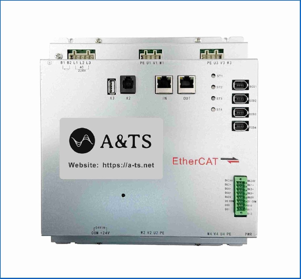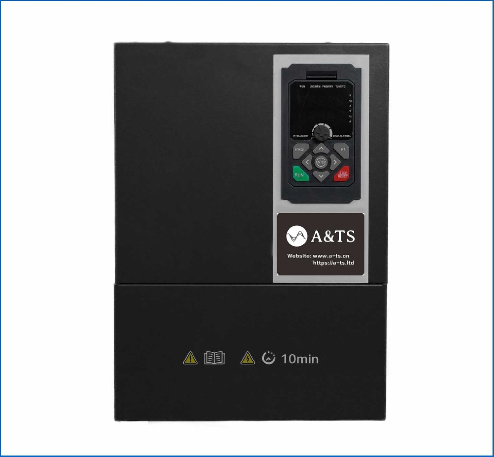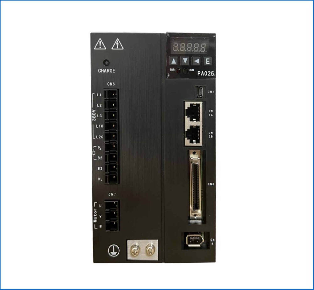

High-Speed Air-Jet Loom Motion & Tension Control System
This application case covers the synchronization, tension control, and commissioning of AC inverters and AC servos for a high-speed air-jet weaving loom operating at up to 1000RPM.
System Architecture Overview
Component | Equipment Type | Control Mode | Interface / Protocol |
Main Drive (Shedding / Reed) | 3.7kW-5.5kW Inverter | Closed-Loop Vector Control | Modbus RTU |
Electronic Let-Off (ELO) | 1.5kW AC Servo Drive | Speed / Torque Hybrid Mode | Pulse / Fieldbus Sync |
Electronic Take-Up (ETU) | 1.5kW AC Servo Drive | Position Control (Electronic Gear) | Fieldbus (CANopen / EtherCAT) |
Warp Tension Sensing | Load Cell / Tension Bar | Feedback Signal | 0-10V Analog to ELO Drive |
Inverter Commissioning (Main Weaving Drive)
The main inverter drives the crankshaft for shedding, reed beating, and shuttle insertion. It requires extremely high starting torque to achieve full speed on the first stroke ('first-pick' capability) to prevent starting marks on the fabric.
1. Hardware & Wiring Setup
Connect a dynamic braking resistor (100% duty-cycle rated) to handle rapid stopping for yarn breakage signals.
Wire the main shaft encoder (1024-4096PPR) directly to the inverter's encoder expansion card.
2. Key Parameter Settings
Parameter | Recommended Setting | Rationale |
Control Mode | Closed-Loop Vector (FVC) | Delivers 200% torque at 0Hz for fast acceleration |
Fast-Start Torque Boost | 150% - 200% Initial Torque | Ensures the loom reaches full operating RPM on the very first pick |
Acc / Dec Time | 0.1s/0.1s (S-Curve) | Instantaneous start and emergency stop within 1 pick cycle |
Braking Torque | Maximum DC Injection / Braking | Rapidly halts the main reed before impact if yarn insertion fails |
3. Autotuning & Testing
Perform a Full Dynamic Motor Autotune with the motor decoupled from the loom crankshaft to map stator resistance, rotor time constant, and leakage inductance.
Test ‘first-pick’ acceleration: Trigger a start command and measure the time to hit 1000 ext{ RPM} using an oscilloscope trace of output frequency vs. current.
Servo Commissioning (Electronic Let-Off & Take-Up)
The Electronic Let-Off (ELO) releases the warp yarns from the warp beam while maintaining constant yarn tension. The Electronic Take-Up (ETU) pulls the finished cloth at a precise linear speed to control the pick density (threads per inch).
[Warp Beam] ──(ELO Servo)──> [Weaving Zone] ──(ETU Servo)──> [Cloth Roll]
│ ▲
Load Cell Main Reed
│ │
└───────── [Tension PID] ────────┘
1. Electronic Take-Up (ETU) Setup
Control Mode: Position Mode locked to Main Inverter pulse output via Electronic Gear Ratio (N/D).
Pick Density Adjustment: Scale the ratio so that for every 360 circ main crank rotation, the take-up roller advances by exactly the desired pick distance (e.g., 0.25mm for 100 picks/inch).
2. Electronic Let-Off (ELO) Tension Loop Setup
Parameter | Recommended Setting | Rationale |
Control Mode | Speed Mode with Tension PID | Adjusts beam rotational speed based on warp tension feedback |
Beam Diameter Track | Math-based D(t) Calculation | Automatically scales motor speed as the warp beam unwinds from full to empty |
Tension PID Gain | Low-to-Medium Initial | Prevents tension oscillation caused by mechanical beating pulses |
Integral Time | Active Smoothing | Eliminates steady-state tension droop during long weaving runs |
3. Servo Tuning Steps
Step 1: Beating Filter Setup (Notch / Low-Pass) Every time the reed beats against the cloth fell, the tension load cell reads a massive, sharp tension spike. Apply a Digital Low-Pass Filter (5-10 Hz) or Notch Filter on the analog tension input to prevent the ELO servo from over-reacting to cyclic reed impacts.
Step 2: Dual Servo Synchronization (ELO + ETU) Verify that when the main inverter stops, both ELO and ETU stop simultaneously without lag. If ELO stops slower than ETU, warp threads will snap; if ETU stops slower, a loose ‘stop mark’ will appear on the fabric.
Step 3: Diameter Variable Gain Tuning As the warp beam decreases from varnothing 800 mm to varnothing 150mm, system inertia drops drastically. Enable Inertia Adaptation Gain in the servo so loop gains scale down proportionately as the roll empties.
System Calibration & Validation
1.Stop Mark Prevention Test: Perform 20 consecutive start/stop cycles at 1000RPM. Inspect the woven fabric under a magnifying glass for density variations at the stop lines. Adjust the ELO "Reverse Compensation Angle" upon start to balance yarn slack.
2.E-Stop Yarn Protection: Cut a warp thread manually while running at full speed. Confirm that the optical yarn sensor triggers the main inverter's dynamic braking unit to stop the reed in under 100ms, before completing a full stroke.